Handling overload#
Any system has a specific maximum capacity under a certain type of workload. The underlying virtual or physical hardware limits this capacity.
Origins#
The major components with hard limits are:
-
Processor: if too many processes are competing for CPU time, there will come a time when the operating system scheduler will have to pause certain processes and delay them.
-
Memory size: memory is different from processor and disk in the sense that it is a hard limit. If a process cannot allocate memory, it will simply crash. Operating system delay this from happening by using swap: using disk as a trade-off between speed and crashes.
-
Memory bandwidth: although harder to quantify and observe, memory bandwidth plays an important role in certain applications that manipulate large amounts of date in memory. The memory bandwidth limit may be hit and as a result, memory access will be delayed.
-
Storage bandwidth: any storage system has a finite bandwidth similar to memory. Once this limit is exceeded, the operating system queues the read/write requests.
-
Disk operations: in addition to raw bandwidth, a storage system has a limit on the number of read/write operations it can process. This limit is hard to quantify as it depends on the request size and mix. Again, queuing starts to happen when this limit is reached.
-
Network bandwidth: although it is rare to hit this limit, it is not impossible. Sustained transfer of large amounts of data can saturate the network interfaces and cause a process or other processes to stall.
Modeling#
Considering an API based synchronous system, we have a number of clients sending a number of requests and waiting for responses.
We define the saturation as the ratio of incoming requests divided by the capacity of the system.
Suppose
- r is the request rate in requests/second
- R is the maximum request rate the system is designed to handle
- S is the saturation
$$ S = \frac rR $$
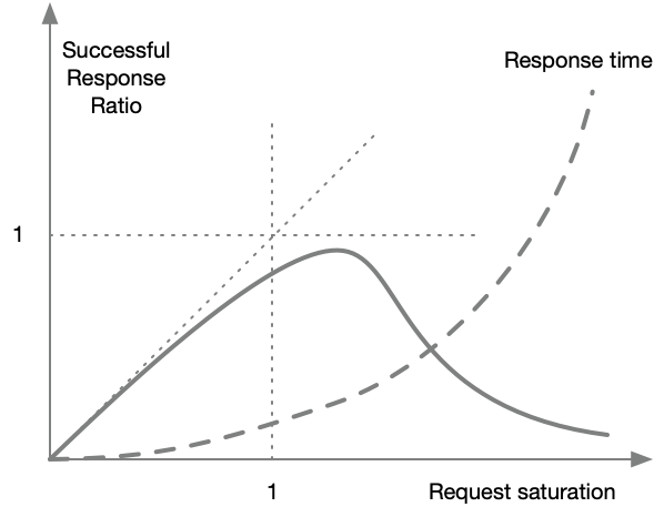
Behavior under stress#
As the incoming traffic r approaches the limit R or S approaches 1, two things start to happen:
- Requests start to fail.
- Response time increases exponentially.
If we continue increasing the request rate, the system spends its time on managing resources and managing errors, barely handling any good requests.
If we still keep increasing traffic, the system will crash and barely process any traffic.
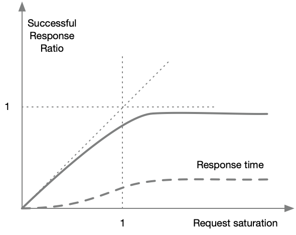
Solutions#
The solution to this problem is to implement rate limiters that will immediately return an error when a system is saturated.
When such a limiter is installed, when the traffic reaches the saturation limit, the system still serves the traffic it is designed to serve and refuses the rest, relaying an HTTP 429 error to the origin client.
Although the success rate will go down with increasing traffic, at least the system would still be handling the traffic it is designed to handle.
Latency would also be limited to a ceiling value.
Multiple rate-limiters need to be put in place:
- A global limiter that protects the service as a whole from being drowned with traffic.
- A per-client limiter that prevents a single client from starving a service.
These limiters are ideally installed service-side, however, this is not always possible: some systems may be old and lacking proper protection infrastructure or not designed for robustness.
In any case, it is always a good idea to implement rate-limiters client side to that the total load inflicted on the service is limited.
Implementation#
Suppose there are M clients that need to connect to N services. The clients can be mobile applications, web applications, external services or other internal services. They are all considered as clients as they initiate connections and issue requests.
Mesh architecture#
Also called point-to-point In this architecture any client connects directly to any service.
flowchart LR
  C1[Client 1]
  C2[Client 2]
  CM[Client M]
  S1[Service 1]
  S2[Service 2]
  SN[Service N]
  C1 --> S1
  C1 --> S2
  C1 --> SN
  C2 --> S2
  CM --> S1
  CM --> SN
Centralized architecture#
In this architecture, all clients connect to a central router which then connects to the various servers. This is usually implemented as a load balancer or an API Gateway.
flowchart LR
  C1[Client 1]
  C2[Client 2]
  CM[Client M]
  S1[Service 1]
  S2[Service 2]
  SN[Service N]
  R[Router]
  C1 --> R
  C2 --> R
  CM --> R
  R --> S1
  R --> S2
  R --> SN
Comparison#
For a robust system, a number of protections are required for both architectures. In a mesh network, each service itself needs to implement the limits. This has many challenges as the system would need to be very conservative.
Concurrency limiting#
In normal circumstances, this limiter should not be required. However, whenever there is an issue on a service, its response time increases and the number of open connections or concurrent requests increases as well. This trickles back to the clients which in turn have numerous open connections.
Let’s take a numerical example. Suppose a service has an average response time of 100 ms and the rate is limited to 100 requests per second. According to Little’s Law:
$$ W=0.1\ s$$
$$\lambda = 100\ tps$$
$$L = \lambda W = 100*0.1 = 10$$
So under normal circumstances, a total of 10 connections are open on average.
Whenever there is an issue on the service that does not cause it to fail completely but respond with a very long delay, the number of connections will increase drastically. In our example, if the average response time increases to 5 seconds, the average number of connections becomes:
$$ L = \lambda W = 100*5 = 500 $$
In turn, this large number of connections may affect the service negatively and cause it to enter a failure loop.
By limiting the number of connections to, say 20, the system can support a moderate increase in response time while still protecting the services and the clients.
Fairness#
Implementing rate and connection limiting globally is not enough to ensure a robust system. In some cases, a single client may be misbehaving, or under attack and generating a large number of requests. The rate-limiter kicks-in and other clients will start failing as well.
The solution is to have a rate-limiter per client set to lower level than the global limiter.
Conclusion#
Protecting services in an essential part of robust system architecture. Any problem with any service or client should not bring the whole system down.
The rules to maximize robustness are:
R1. Implement a global rate limiter R per service.
R2. Implement a rate-limiter Ci « R per client.
R3. Implement a connection limiter L per service
R4. Implement a connection limiter Li « L per client